📢 Development Notice: This project will no longer receive feature updates. A new NodeMCU 12E (ESP8266) version: Smart Aquarium V3.1 is ready & ESP32 version: Smart Aquarium V4.0 is under development that supports more powerful customization options and advanced monitoring features for aquarium inhabitants. Be the first ones to try it out and give feedbacks! 🚀


HIGH VOLTAGE electricity involved! Use at your own risk. Work under proper supervision if you are a minor. I take no responsibility for any accidents that may occur from using this code.
- Modern responsive web interface
- Asynchronous webserver for better performance
- Real-time page updates using JavaScript XMLHttpRequest
- ESP-NOW time broadcasting to other ESP devices
- Multiple control modes:
- Automatic (time-based)
- Power Saver
- Timer
- Manual
- Intuitive status display on web interface
- Solid State Relay support for reliability
- Over-the-Air (OTA) updates
- Automatic time synchronization
- Visual feedback and WiFi signal indicators
Add this URL in Arduino IDE:
http://arduino.esp8266.com/stable/package_esp8266com_index.json
File → Preferences → Additional Boards Manager URLs
Install these libraries in Arduino IDE:
https://github.com/NorthernWidget/DS3231
https://github.com/dvarrel/ESPAsyncTCP
https://github.com/ESP32Async/ESPAsyncWebServer
Library Manager → Search and Install, or download ZIP and add manually
Note: Remove any conflicting libraries from your Arduino libraries folder before installation to avoid compilation errors.
Important: Incorrect network configuration may result in connection issues. Consult your network administrator if unsure.
Note: Ensure to update your WiFi credentials in the code before uploading to the NodeMCU.
| NodeMCU | Device |
|---|---|
| D1 | SCL |
| D2 | SDA |
| 3.3V | VCC |
| GND | GND |
Note: Both I2C devices share the same pins. For I2C address conflicts, adjust pull-up resistor values.
| NodeMCU | Relay |
|---|---|
| D3 | IN1 |
| D5 | IN2 |
| D6 | IN3 |
| D7 | IN4 |
Important: Do not fetch power from ESP GPIO Pins for relay board. Connect GND between NodeMCU, Relay and power supply.
For detailed wiring and connection diagrams, please refer to the project schematics.

Circuit Diagram
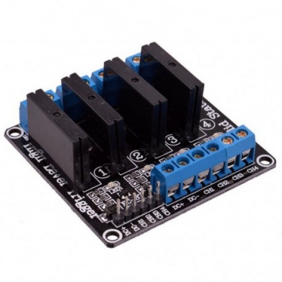 Relay Board 4 Channel 5V SSR 250V 2A with Resistive Fuse |
 RTC Module DS3231 I2C Precision RTC |
 Microcontroller NodeMCU-ESP8266 ESP12E Development Board |
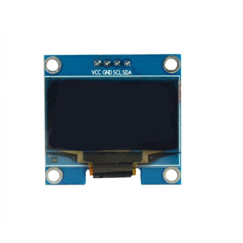 OLED Display 1.3" I2C I2C 128x64 Any Color |
 Responsive Web Dashboard |
|
|
|
We welcome contributions! Here's how you can help:
- 🔀 Fork the repository
- 👩💻 Create your feature branch
- ✨ Make your changes
- 📝 Open a Pull Request
Here's what more can be done:
- 📱 Mobile App Integration
- 🌡️ Temperature Control
- 💧 Water Level Monitoring
- 🔄 Auto Water Change System
See our Issues page for detailed roadmap and planned features.
See Issues for planned features and improvements.
Click to expand detailed license information
| GNU General Public License v3.0 Details | |
|---|---|
| Permissions |
✅ Commercial use - Use for business purposes ✅ Modification - Modify the code ✅ Distribution - Share the code ✅ Patent use - This license provides an express grant of patent rights from contributors |
| Conditions |
📝 License and copyright notice - Include the original license and copyright 📝 State changes - Document all changes made to the code 📝 Disclose source - Source code must be made available when distributing 📝 Same license - Modifications must be released under the same license |
| Limitations |
|
This is a copyleft license that requires anyone who distributes your code or a derivative work to make the source available under the same terms.
For complete license text, see LICENSE